What is an Absorbing Clamp?
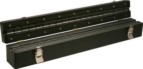
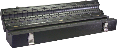
The absorbing clamps are made up of four main parts that work together:
• An RF-current transformer for measuring the current.
• The absorber chain, made up of split, finely ground ferrite rings, decouples the mains effect and provides a defined RF-termination to the line of the EuT being tested.
• The second set of ferrite rings decouples the current transformer from the receiver's asymmetric (common-mode) impedance.
• Easy-to-open non-metalic housing featuring wheels for effortless mobility
Absorbing Clamps to measure EMI Emissions according to CISPR 13 [EN 55013], CISPR 14 [EN 55014], and CISPR 32 [EN 55032]. The absorbing clamps, also known as ferrite clamps, are used for measuring disturbance power on power input lines as well as other auxiliary I/O lines. The absorbing clamp measurement method (ACMM) is described in Clause 7 of CISPR 16-2-2. The CLA-050 and CLA-150 consist of a broadband current transformer (30 MHz to 1 GHz) and two sets of ferrite rings.
The line(s) under test are routed through the current transformer and one of the set of ferrite rings. The ferrite rings act as a broadband RF power absorber, isolate the current transformer from disturbances on the mains and establish asymmetric (common-mode) impedance. Each of these ferrites is split into two halves, with one half mounted in the absorbing clamp base and the other half mounted in the hinged top cover.
When the clamp is open, the line(s) under test are easily placed inside the ferrites' bottom halves. When the clamp is closed, the two halves meet, forming a ring around the line(s) under test. The coaxial line connecting the current transformer to the clamp
Contact Us
Get a Quote


