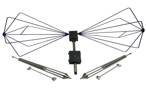
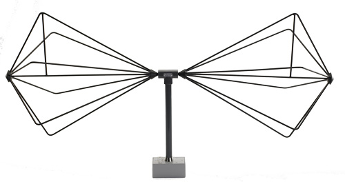
Biconical Antenna construction + How Biconical Antenna works + Biconical Antenna applications
Two conical elements, usually composed of conductive material like metal, are arranged vertically, facing each other to form a biconical antenna. The cones are linked to the coaxial cable, or other transmission line, which supplies the antenna with the radio frequency signal. The antenna's working frequency range and radiation pattern are determined by two crucial design parameters: the length of the cones and the angle between them, or the apex angle.
The biconical antenna distributes energy into free space as an RF signal travels along the cones. Uniform coverage in the horizontal plane is produced by the radiation spreading out in an omnidirectional pattern perpendicular to the antenna's axis due to the cones' design. Because of this, biconical antennas can be used in situations where minimum directionality and wide coverage are required.
The wideband performance of biconical antennas is one of their primary benefits. The antenna may successfully transmit and receive signals across a wide frequency range without experiencing appreciable signal deterioration because of its relatively constant impedance. The tapered structure of the cones gives the antenna its wideband characteristic, allowing it to function well over a broad range of wavelengths and support numerous resonant modes.
Biconical antennas are used for emissions and immunity testing to meet various EMC standards specified by FCC, CISPR and EN. The broadband characteristics of the biconical antenna make it a good choice for making sweep measurements and for automated measurement systems. Normally, tuned dipole antennas are used for EMC site attenuation measurements for better accuracy. However, the biconical antenna is easier to use for vertical site attenuation measurements, because of the long dipole element lengths at lower frequencies (5 meters at 30 MHz).
According to ANSI 63.4 specification, calibrated biconical, and a log periodic antennas can be used for site attenuation measurements. The calibration data provided with each antenna is used to calculate field strength measured for the selected frequency. The antenna factor (dB/m) is added to the measured output (dBV) displayed by the EMI meter to obtain field strength (dBV/m).
The microwave biconical antenna is a precisely tuned, linearly polarized, mini-biconical dipole antenna, operating at the low end of the microwave band over the frequency range of 1 to 6 GHz. It may be used as either a transmitting or receiving antenna. The microwave biconical antenna (such as Com-Power's ABM-6000) was specifically designed to comply with radiation pattern specifications detailed in CISPR 16-1-4(section 8.2.2.1), and is intended to be used as the transmit source antenna for site validations above 1 GHz for radiated emissions test sites, such as OATS (open area test sites), anechoic and semi-anechoic chambers.
Contact Us
Get a Quote


