
Compact Log Periodic Antenna
- ALC-100 is lightweight and compact for easy transport and storage. It has a frequency range of 300 MHz to 1 GHz.
- It is ideal for offsite EMC testing or testing inside small EMC chambers.
- It is part of the ANK series antenna kits.
- Every antenna is independently calibrated with NIST traceability in accordance with ANSI C63.5. Both the certificate and the calibration data are included.
- On request, recognized ISO 17025 approved calibration is also offered.
- The ALC-100 can also be used in conjunction with an RF power amplifier (up to 50 watts) to generate RF fields associated with RF immunity tests
Features
- ▸ Continuous broadband sweep without tuning — covers 300 MHz to 1 GHz (usable from 200 MHz) as a single continuous antenna; replaces 15–20 tuned-dipole element changes and shrinks a typical sweep from hours to minutes.
- ▸ Compact and lightweight design — only 2 lbs (0.9 kg) and 13 inches shorter overall than the AL-100, making it the preferred LPDA for off-site work, small chambers, and pre-compliance benchtops where space matters.
- ▸ Solid stainless steel elements — element rods are solid stainless steel rather than tubular, eliminating internal corrosion paths and surviving repeated transport, handling, and outdoor exposure.
- ▸ Heavy-gauge corrosion-resistant aluminum feeder tubes — rugged enough for daily lab use and continuous outdoor exposure on OATS facilities under extreme weather.
- ▸ Hinged polarization-change mount — integrated hinge mechanism allows the operator to switch between horizontal and vertical polarization in seconds without re-mounting the antenna.
- ▸ Transmit and receive capability — functions as a receiving antenna for emissions testing and as a transmitting antenna for radiated immunity testing with up to 50 W input power.
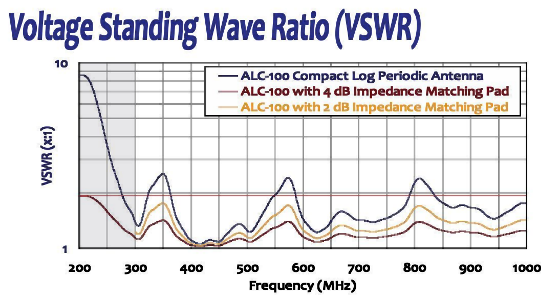
- ▸ Optional 2 dB or 4 dB impedance-matching pads — available factory-fitted matching pads further flatten VSWR and improve return loss to satisfy the most stringent measurement requirements.
- ▸ NSA calibration alternative for OATS / SAC — a pair of ALC-100 antennas can be used in lieu of tuned dipoles for Normalized Site Attenuation calibrations, eliminating the time-consuming process of tuning element lengths at each discrete frequency.
- ▸ Standard 1/4"-20 tripod/mast mounting — mounting assembly accepts the Com-Power AT-812 Antenna Tripod, AM-400 Antenna Mast, or any compatible support structure.
- ▸ Regulatory compliance applications — suitable for qualification-level measurements per FCC, CISPR, EN, ETSI, FAA, MIL-STD-461, RTCA DO-160, FDA, and SAE Automotive standards.
- ▸ General-purpose RF utility — useful for site comparisons, shielding effectiveness testing, field monitoring, and site surveys beyond formal compliance work.
- ▸ Individually calibrated, NIST-traceable — calibrated per ANSI C63.5; calibration data and certificate ship with each unit; ISO 17025 accredited calibration available on request.
- ▸ Three-year standard warranty — backed by manufacturer support.
Specifications
| Product Name | Compact Log Periodic Antenna |
|---|---|
| Frequency Range | 300 MHz to 1 GHz (usable from 200 MHz) |
| Polarization | Linear |
| Nominal Impedance | 50 Ω |
| Power Handling | 50 Watts (continuous) |
| Connector | N-type (female) |
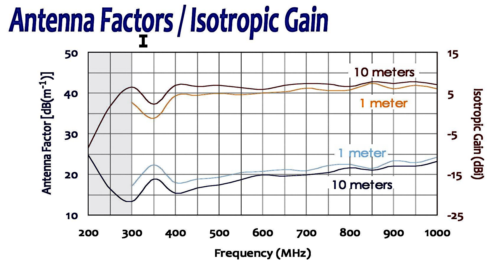
| Antenna Factor | 13.3 to 23.2 dB(m-1) [average: 19.3] |
| Isotropic Gain | 2.1 to 7.8 dBi [average: 6.6] |
| VSWR | 1.05 to 2.52 : 1 [average: 1.57] |
| Return Loss | 7.3 to 31.0 dB [average: 16.4] |
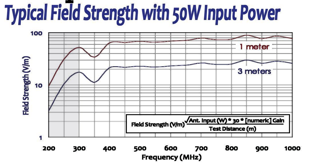
| Radiated Field Strength | See typical field strength graph (with 50 W input power) |
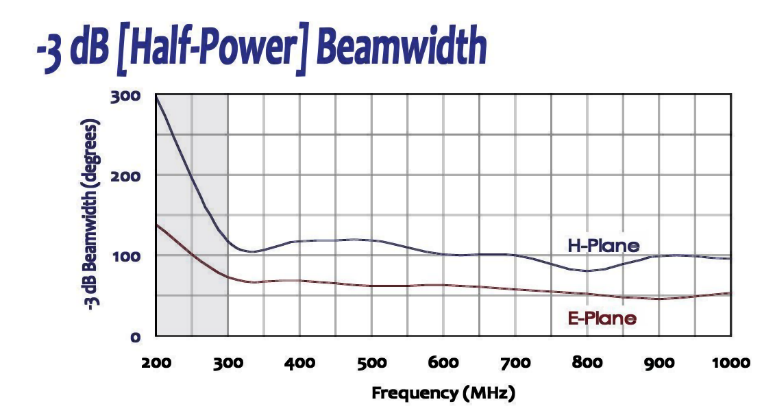
| -3 dB Beamwidth | See typical -3 dB beamwidth graph (E-plane and H-plane) |
| Applicable Standards | FCC, CISPR, EN, ETSI, FAA, MIL-STD-461, SAE, etc. |
| Calibration | Individually calibrated per ANSI C63.5, NIST traceable |
| Dimensions (H × W × D) | 21.5" × 5.1" × 25.5" [54.6 × 13 × 64.8 cm] |
| Weight | 2 lbs [0.9 kg] |
All values are typical, unless specified. All specifications are subject to change without notice.
🔍 Not Sure Which Antenna You Need?
Compare all Com-Power antenna models side-by-side with our interactive selection tool. Filter by frequency range, antenna category, application, polarization, and power handling to find your perfect match.
Compare All Antenna Models →ALC-100 Compact Log Periodic Antenna – Frequently Asked Questions
1. What is the ALC-100 compact log periodic antenna and what is it primarily designed to do in EMC testing?
The ALC-100 compact log periodic antenna is a broadband linearly polarized log periodic dipole array (LPDA) intended for EMC and EMI measurements over 300 MHz to 1 GHz, with practical usability beginning around 200 MHz. Its main purpose is to provide a stable, repeatable broadband antenna solution for radiated emissions measurements, engineering pre-compliance work, troubleshooting, and selected radiated immunity applications. In practical EMC workflows, the ALC-100 is especially valuable where an engineer needs one antenna that can cover a large portion of the common commercial EMC frequency band without requiring multiple antenna changes. That makes it useful not only for formal measurement setups, but also for day-to-day development work where speed, portability, and measurement consistency matter.
2. Why would an engineer choose the ALC-100 instead of a larger log periodic antenna?
The ALC-100 is chosen when compact size, lower weight, easy handling, and flexibility of setup are more important than maximum physical aperture or higher gain from a larger antenna. In many engineering labs, the limiting factor is not whether a larger antenna exists, but whether it can be positioned easily inside a small semi-anechoic chamber, benchtop pre-compliance area, temporary test setup, or on-site field location. A larger log periodic antenna may offer stronger gain or better performance in larger compliance environments, but it can also be more cumbersome, harder to transport, and less convenient when repeated repositioning is required. The ALC-100 is a very practical choice when an EMC engineer wants a broadband antenna that is fast to deploy, easier to store, and well suited for repeated engineering investigations rather than only large, fixed lab setups.
3. What types of real-world EMC measurements is the ALC-100 best suited for?
The ALC-100 is well suited for radiated emissions scans, engineering diagnostics, product troubleshooting, cable radiation checks, enclosure investigations, shielding comparisons, field strength observations, and pre-compliance measurements. In real product development, engineers often use an antenna like this to compare emissions before and after a design change, such as adding a ferrite, changing a cable route, modifying a PCB ground connection, updating enclosure bonding, or redesigning a power stage. It is also very useful in programs where several prototypes must be checked quickly to determine which version is most likely to pass formal EMC compliance. Because it covers a broad frequency range in one antenna, it can support both initial problem discovery and repeated comparative testing during corrective design work.
4. Why is compact size such a meaningful advantage in modern EMC work?
Compact size matters because many real EMC problems are investigated outside ideal compliance-lab conditions. Engineers frequently work in constrained spaces such as prototype labs, partially absorber-lined rooms, mobile validation environments, customer sites, or smaller chambers where a large antenna is inconvenient. A more compact antenna like the ALC-100 is easier to rotate, easier to switch between horizontal and vertical polarization, easier to move closer or farther from the equipment under test, and easier to mount on smaller tripods or portable masts. That may sound like a convenience feature, but in practice it directly affects productivity. When antenna positioning is simpler, engineers perform more measurement iterations, gather more useful comparison data, and reach root-cause conclusions more quickly.
5. How does the ALC-100 compare with a biconical antenna in EMC test planning?
A biconical antenna is usually the better choice for lower-frequency radiated emissions work, especially below roughly 200 MHz to 300 MHz, while the ALC-100 becomes more appropriate in the higher portion of the common commercial EMC band. If a lab is measuring across a wide compliance range that begins near 30 MHz, a biconical antenna may still be necessary for the lower band. However, once the application is focused on frequencies from about 200 MHz upward, especially for FCC, CISPR, EN 55032, and similar broadband product emissions work, the log periodic format becomes more advantageous. It generally provides better directivity and more practical broadband behavior in that region. So the decision is not usually “which antenna is better overall,” but rather “which antenna is better for the specific frequency region and measurement objective.”
6. How does the ALC-100 compare with the ALP-100 in practical Com-Power antenna selection?
The ALC-100 and ALP-100 may appear similar because both are log periodic antennas, but they are aimed at somewhat different priorities. The ALC-100 is the more compact, lightweight, portable, engineering-friendly option for emissions work, field investigations, and moderate transmit applications. The ALP-100 is the better choice when the program requires substantially higher RF power handling for more serious radiated immunity field generation. In simple terms, if the priority is ease of use, chamber flexibility, and fast engineering work, the ALC-100 is often the better fit. If the priority is high-power broadband immunity testing and stronger transmit performance, the ALP-100 is the more suitable antenna. This distinction is important for buyers because choosing only by frequency range can lead to the wrong antenna for the actual test objective.
7. Can the ALC-100 be used for both radiated emissions and radiated immunity testing?
Yes. The ALC-100 can serve as a receiving antenna for radiated emissions measurements and can also be used as a transmitting antenna for lower-to-moderate radiated immunity applications when paired with an RF power amplifier, up to its rated power handling capability. This makes it useful in engineering labs that want one antenna to support both receive-side investigation and selected transmit-side validation. That said, the key decision point is field strength requirement. If the lab must generate very demanding compliance-level fields over broad frequency ranges at standard distances, then a more powerful antenna may be the better option. But for development labs, troubleshooting teams, smaller setups, and selected immunity work, the ALC-100 provides useful dual-purpose capability.
8. How does the ALC-100 improve in-house pre-compliance testing during product development?
The ALC-100 helps teams identify emissions risks before formal outside-lab testing, which is one of the most cost-effective uses of EMC equipment. During development, engineers can use it to scan prototype systems, compare enclosure variations, observe the effect of cable routing, and verify whether design corrections are moving the product in the right direction. In many organizations, the goal of in-house pre-compliance is not to claim certified pass/fail status, but to reduce surprises later. The ALC-100 supports that goal well because it gives repeatable broadband measurements over an important compliance band while being practical enough to use frequently. The more often engineers measure, the earlier they catch problems, and the lower the redesign cost becomes.
9. What does a typical ALC-100 pre-compliance setup look like in a real engineering lab?
A typical setup places the ALC-100 on a tripod, small mast, or chamber antenna stand, connected to a spectrum analyzer, EMI receiver, or analyzer plus preamplifier chain. The equipment under test is placed on a non-conductive table or representative support surface, and the engineer performs frequency sweeps while changing antenna height, orientation, cable placement, product modes, and sometimes grounding conditions. A practical workflow often includes comparing multiple operating states, such as idle mode, maximum data activity, motor operation, or wireless activity, to determine worst-case emissions. The ALC-100 is especially useful here because it can be repositioned easily and does not impose the handling burden of a larger antenna, which encourages more measurement iterations and better engineering conclusions.
10. Why does individual ANSI C63.5 calibration with NIST traceability matter for the ALC-100?
Calibration matters because EMC measurements are only useful when the relationship between the antenna output and the actual electric field is known with reasonable confidence. The ALC-100 is described as being individually calibrated per ANSI C63.5 with NIST traceability, which means the antenna factor data provided with the antenna can be used to translate measured receiver voltage into field strength more reliably. For engineering teams, this improves confidence that internal measurements are meaningful and correlate better with formal compliance lab results. For quality systems and regulated environments, the calibration record also supports traceability, documentation, and measurement defensibility. In other words, calibration is not just a paperwork feature; it is part of how the measurement becomes actionable.
11. How important is polarization control when using the ALC-100?
Polarization control is extremely important in EMC testing because radiated emissions and susceptibility often vary significantly between horizontal and vertical antenna orientations. A product may appear relatively quiet in one orientation and much worse in the other, depending on cable geometry, PCB current loops, enclosure seams, and structural resonances. A linearly polarized antenna like the ALC-100 gives engineers controlled, repeatable measurement orientation. In real use, changing polarization is not just a standards ritual; it is one of the main ways engineers discover worst-case radiating structures. That makes easy polarization changes an important practical advantage in troubleshooting and pre-compliance work.
12. Can the ALC-100 be used for shielding effectiveness and enclosure evaluation work?
Yes. The ALC-100 can be used in shielding effectiveness measurements, comparative enclosure leakage studies, and structural EMC investigations. For example, engineers can use it to compare the RF leakage impact of different gasket materials, seam treatments, grounding straps, door closures, or panel bonding strategies. In practical design work, shielding is often evaluated comparatively rather than absolutely: one design version is measured against another to determine which one reduces leakage more effectively. A compact broadband antenna like the ALC-100 is useful for that type of engineering work because it is easy to position and can cover a meaningful portion of the spectrum in one setup.
13. What standards and compliance environments is the ALC-100 relevant to?
Based on the provided page information, the ALC-100 is positioned for use across standards and programs such as FCC, CISPR, EN, ETSI, MIL-STD-461, RTCA DO-160, SAE automotive, and medical or regulated product environments. That broad relevance does not mean one antenna alone replaces every other antenna needed in a full-service compliance lab, but it does mean the ALC-100 fits naturally into many common EMC workflows. It is especially relevant where a lab needs broadband measurements in the mid-to-upper commercial EMC band and values portability and compactness.
14. What practical RF and mechanical interface details matter most in daily lab use?
The ALC-100 uses a 50-ohm nominal impedance and a Type-N female connector, which are common and practical choices in EMC environments. These standard interfaces help the antenna integrate easily with existing cables, preamplifiers, receivers, analyzers, and moderate-power amplifiers. The light weight also reduces the demand on mounting hardware and makes the antenna easier to reposition during repeated measurement sequences. These daily-use details matter more than they may seem, because the easier an antenna is to connect, mount, and move, the more effectively it supports real engineering work rather than remaining a specialized tool used only occasionally.
15. When is the ALC-100 the right buying decision, and when might another antenna be better?
The ALC-100 is the right choice when a lab wants a compact broadband antenna for 300 MHz to 1 GHz work, with strong usefulness in pre-compliance testing, emissions troubleshooting, smaller chambers, mobile EMC setups, and general engineering investigation. Another antenna may be better if the application is dominated by lower frequencies, where a biconical is more appropriate, or by higher-power immunity requirements, where a more powerful log periodic such as the ALP-100 is the better fit. This is why the buying decision should be based not only on frequency range, but also on whether the primary need is receive-side flexibility, transmit power capability, chamber size compatibility, and portability.
16. Why is the ALC-100 a strong long-term tool for engineering labs rather than just a small accessory antenna?
The ALC-100 is a strong long-term investment because it combines broadband coverage, practical portability, standards-oriented calibration, and real usefulness in daily EMC workflows. Many antennas look good on paper but are too large, too specialized, or too inconvenient for frequent engineering use. The ALC-100 is valuable precisely because it is likely to be used often. It supports routine scans, comparative design checks, site investigations, and repeated troubleshooting work that happens before and between formal compliance events. In that sense, it is not merely a small antenna; it is a practical engineering antenna that helps teams reduce compliance risk and speed up product development decisions.
Application Notes (PDF)
- AN-107 — What is Antenna Factor?
- AN-106 — Use of Antenna Factor for EMC Measurements
- Selecting the Right EMI Antenna
- Considerations when Selecting an Antenna for RF Immunity Testing
- EMC Antenna Calibration Requirements, Methodologies, and Best Practices
- NIST Antenna Calibration Services — Com-Power Capabilities and Traceability
- Com-Power EMC Antenna Product Line — Complete Specifications
- Accounting for Ambient Noise
Interactive Tools
- Antenna Finder Wizard
- Com-Power Antenna & Field Strength Calculator
- Com-Power EMC Compliance Limits Calculator
- Com-Power Cable Loss & Attenuation Calculator
- Com-Power VSWR / Return Loss / Mismatch Loss Calculator
- Com-Power Free Space Path Loss & Link Budget Calculator
Industry Applications
- EMC Considerations for IoT and Smart Home Devices
- Automotive EMC Testing — ISO 11452 / CISPR 25
- 5G Equipment EMC Testing — New Challenges in EMC Compliance
- Medical Device EMC Compliance — IEC 60601-1-2 Essentials
- EV Charging Systems — EMC Requirements and Compliance
Blog Articles


Quote Request
Other EMC Test Equipment
- Absorbing Clamps
- Antenna Kits
- Antenna Masts - Automated and Manual
- Antennas
- Bulk Current Injection probes
- CDNs - Coupling Decoupling Network
- Comb Generators
- Conducted Immunity Test Systems
- Current Monitor Probes
- Current Probe Calibration Fixtures
- EM Clamps
- Feed Through Capacitor
- ISNs - Impedance Stabilization Network
- LISNs - Single Phase
- LISNs - TEMPEST
- LISNs - Three Phase
- Magnetic Field Generator
- Near Field Probes
- Power Amplifiers
- Pre-compliance Emissions Test Systems
- Preamplifiers
- Spectrum Analyzers
- Surge Generators
- System Controllers
- Transient Limiters
- Tripods For EMC
- Turntables