
Van Veen Triple Loop Antenna
- The ALT-930-2M is a Van Veen Triple Loop Antenna (Loop Antenna System) for CISPR 15 / EN 55015 radiated disturbance measurements of lighting equipment from 9 kHz to 30 MHz, designed per CISPR 16-1-4 Annex C.
- Three mutually perpendicular 2-meter diameter loops (X / Y / Z axes) capture magnetic field emissions in all three orthogonal axes — no EUT rotation needed.
- Loops are RG-223/U coaxial cable inside flexible 1″ PEX pipe, supported by a fiber glass / plastic structure on swivel casters for easy mobility without disassembly. 50Ω BNC female I/O.
- Integrated CS-450 four-channel coaxial switch selects the active loop while terminating the other two into 50Ω. Local front-panel control or remote operation via fiber optic interface (optional RLI-100 kit).
- Built-in switchable 150 kHz high-pass filter rejects mains-frequency interference when measuring the 150 kHz–30 MHz CISPR 15 band, lowering the noise floor and protecting the receiver front end.
- CISPR 15 / EN 55015 compliance testing of lighting equipment — LED bulbs, drivers, ballasts, fluorescent fixtures, and similar products; EUT placed at the approximate center of the loop structure.
- Optional ALT-930-CKIT Calibration Kit — balun-dipole transmitting antenna (per CISPR 16-1-4), mounting structure, and 10-meter RG-223/U cable for in-house calibration of the LAS.
- Individually calibrated per CISPR 16-1-4 with NIST traceability. ISO 17025 calibration available on request. Operating range 0° to 40° C, 65.5 lbs (29.7 kg). Three-year warranty.
Features
- ▸ CISPR 15 (EN 55015) Loop Antenna System for lighting equipment radiated disturbance measurements — the only purpose-built antenna in Com-Power's lineup specifically designed for CISPR 15 / EN 55015 compliance testing of LED bulbs, ballasts, drivers, fluorescent fixtures, and related lighting equipment.
- ▸ Three mutually perpendicular 2-meter diameter loops — the X, Y, and Z loops form a Loop Antenna System (LAS) per CISPR 16-1-4 Annex C, capturing magnetic field emissions in all three orthogonal axes without requiring EUT rotation between measurements.
- ▸ Frequency range 9 kHz to 30 MHz — covers the full lower-frequency CISPR 15 / EN 55015 disturbance band where lighting equipment switching emissions are most prominent.
- ▸ RG-223/U coaxial cable loops housed in 1″ PEX pipe — high-quality double-shielded RG-223/U coax forms each 2-meter loop conductor; the flexible PEX pipe protects the cable while maintaining geometric stability and electrical transparency.
- ▸ Three current-to-voltage transducers feed a four-channel CS-450 coaxial switch — the integrated CS-450 selects which loop (X, Y, or Z) connects to the EMI receiver while terminating the other two loops into 50Ω, ensuring proper loading and isolation during sequential axis measurements.
- ▸ Local or remote axis switching — CS-450 can be operated locally via front-panel control or remotely via fiber optic interface using the optional RLI-100 Remote Interface Kit, enabling automated test sequences from outside the chamber.
- ▸ Built-in 150 kHz high-pass filter (ON/OFF) — switchable filter on the EMI measurement output rejects below-150 kHz mains-frequency interference when measuring in the 150 kHz–30 MHz CISPR 15 band, improving measurement floor and protecting the receiver front end.
- ▸ Fiber glass / plastic mounting structure on swivel casters — non-metallic structure prevents distortion of the magnetic field; integrated swivel casters allow the entire 2-meter assembly to be moved easily without disassembly.
- ▸ EUT placed at approximate center of the loop structure — per CISPR 15, the lighting equipment under test sits in the geometric center of the three orthogonal loops where the LAS reception is calibrated and uniform.
- ▸ BNC female input/output connectors, 50Ω — standard coaxial interface for connection to spectrum analyzers and EMI receivers.
- ▸ Optional ALT-930-CKIT Calibration Kit — includes a Balun-Dipole transmitting antenna (per CISPR 16-1-4), its mounting structure, and a 10-meter RG-223/U coaxial cable for in-house calibration of the LAS per the standard.
- ▸ Optional RLI-100 Remote Interface Kit — includes the RLI-100 remote interface, a 10-meter fiber optic cable, and two AC adapters (6 V DC, 500 mA), enabling automated remote control of axis switching from outside the test chamber.
- ▸ Individually calibrated per CISPR 16-1-4, NIST traceable — calibration data and certificate ship with each unit; ISO 17025 accredited calibration available on request.
- ▸ Three-year standard warranty — backed by manufacturer support.
Specifications
ALT-930-2M Triple Loop Antenna
| Model | ALT-930-2M |
|---|---|
| Antenna Type | Triple Loop Antenna System (LAS), three mutually perpendicular loops (X / Y / Z) |
| Frequency Range | 9 kHz to 30 MHz |
| Applicable Standards | CISPR 16-1-4, CISPR 15 (EN 55015) |
| Loop Diameter | 2 meters (78.7″) |
| Loop Construction | RG-223/U coaxial cable inside 1″ PEX pipe |
| Coaxial Switch | CS-450 four-channel; selects active loop while terminating the other two into 50 Ω |
| Switch Control | Local (front panel) or remote via fiber optic interface (optional RLI-100) |
| Built-in High-Pass Filter | 150 kHz, switchable ON / OFF |
| Input/Output Impedance | 50 Ω |
| Input/Output Connector | Coaxial BNC (female) |
| Mounting Structure | Fiber glass / plastic, on swivel casters for mobility |
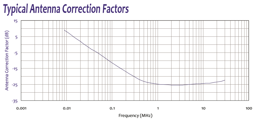
| Antenna Correction Factor | See typical antenna correction factor graph (9 kHz to 30 MHz) |
| Calibration | Individually calibrated per CISPR 16-1-4, NIST traceable; ISO 17025 available |
| Operating Temperature | 0° to 40° C (32° to 104° F) |
| Overall Dimensions (H × W × D) | 2.54 × 2.1 × 2.1 meters [100″ × 82.7″ × 82.7″] |
| Weight | 65.5 lbs [29.7 kg] |
| Warranty | Three-year standard warranty |
ALT-930-CKIT Balun-Dipole Calibration Antenna (Optional)
| Kit | ALT-930-CKIT — includes Balun-Dipole transmitting antenna, mounting structure, and 10-meter RG-223/U coaxial cable |
|---|---|
| Frequency Range | 9 kHz to 30 MHz |
| Applicable Standard | CISPR 16-1-4 (LAS calibration) |
| Balun-Dipole Dimensions (H × W × D) | 1.5 × 0.1 × 0.006 meters [59.1″ × 3.9″ × 0.2″] |
| Loop Construction | RG-223/U coaxial cable on plastic frame |
| Input/Output Impedance | 50 Ω |
| Input/Output Connector | Coaxial BNC (female) |
| Mounting Structure | Fiber glass / plastic |
| Operating Temperature | 0° to 40° C (32° to 104° F) |
| Overall Dimensions (H × W × D) | 1.56 × 1.5 × 0.5 meters [61.4″ × 59.1″ × 19.7″] |
| Weight | 25 lbs [11.34 kg] |
RLI-100 Remote Interface Kit (Optional)
| Kit | RLI-100 Remote Interface Kit |
|---|---|
| Includes | RLI-100 Remote Interface unit, 10-meter fiber optic cable, (2) AC power adapters (6 V DC, 500 mA, unregulated) |
| Function | Remote control of CS-450 axis switching via fiber optic link |
All values are typical, unless specified. All specifications are subject to change without notice.
🔍 Not Sure Which Antenna You Need?
Compare all Com-Power antenna models side-by-side with our interactive selection tool. Filter by frequency range, antenna category, application, polarization, and power handling to find your perfect match.
Compare All Antenna Models →ALT-930-2M Van Veen Triple Loop Antenna System — Frequently Asked Questions
1. What is the Com-Power ALT-930-2M and what is it primarily used for?
The ALT-930-2M is a Triple Large Loop Antenna System (LAS) — also known as a Van Veen loop or Van Veen/Bergervoet triple loop — used to measure the magnetic-field induced current radiated by electrical lighting and similar equipment across 9 kHz to 30 MHz in three orthogonal axes (X, Y, Z). It is the standardized measurement setup specified in CISPR 15 / EN 55015 for radiated disturbance from lighting equipment, described in Annex C of CISPR 16-1-4. The EUT sits in the approximate center of the three mutually perpendicular 2-meter loops, and the induced current in each loop is measured in turn to characterize the radiated magnetic disturbance.
2. What are the ALT-930-2M’s key specifications and system components?
Frequency: 9 kHz – 30 MHz. Measurement axes: X, Y, Z (three mutually perpendicular planes). Loop diameter: 2 m each. Lowest point height: 0.5 m above ground. Loop construction: high-quality RG 223/U coaxial cable housed inside flexible 1″ PEX pipe for mechanical stability. Principle: Van Veen/Bergervoet — each loop is a shielded loop acting as a large current-sensing transformer primary. Transducers: three current-to-voltage transducers, one per loop. Switching: RAS-930 Remote Antenna Switch selects which loop connects to the measuring receiver while terminating the other two loops into 50 Ω. Control: local or remote via fiber-optic interface using optional RLI-100 Remote Interface. Support: non-metallic frame with wheel base for easy erection and repositioning. Calibration: individual per CISPR 16-1-4 with NIST traceability; ISO 17025 available. Optional ALT-930-CKIT calibration kit includes the Balun-Dipole antenna per CISPR 16-1-4 plus 10-meter RG 223/U cable.
3. What is CISPR 15 and why does it require a three-axis loop system?
CISPR 15 (identical to EN 55015) is the international standard for limits and methods of measurement of radio disturbance characteristics of electrical lighting and similar equipment. It applies to LED drivers, fluorescent ballasts, HID ballasts, dimmers, smart lighting controls, signage, and similar products. At 9 kHz–30 MHz, the relevant quantity is the radiated magnetic field disturbance, which a lighting product produces primarily through its switching circuitry. Because the orientation of the EUT’s emissions vector is unknown in advance, the standard requires measurement in all three orthogonal axes — hence the three mutually perpendicular loops. The system measures the induced current in each loop, and the highest reading across all three axes at each frequency is used for comparison with the CISPR 15 limit.
4. Who is Van Veen and why is this antenna named after him?
The Van Veen loop (often called Van Veen/Bergervoet after both contributors) is a measurement geometry developed at Philips Research Laboratories in the Netherlands during the 1990s to address a long-standing problem in lighting EMC: measuring large, free-standing lamp assemblies with consistent, reproducible results across different labs. The Van Veen/Bergervoet principle defines the loop diameter, transducer type, termination impedance, and EUT placement geometry so that any lighting product placed at the loop center produces the same measured current — regardless of the lab or specific mechanical support frame. This principle became codified in CISPR 16-1-4 Annex C and is the basis for all modern LAS systems, including the ALT-930-2M.
5. Which standards and agencies accept the ALT-930-2M?
• CISPR 15 (international) and its harmonized versions worldwide
• EN 55015 (European Union) — mandatory for CE marking of lighting equipment
• CISPR 16-1-4 Annex C — the equipment specification that defines the Van Veen LAS
• FCC Part 18 — U.S. consumer lighting equipment emissions
• ANSI C63.4 — general unintentional radiator emissions methods referenced for consumer lighting
• IEC 61547 — lighting equipment immunity (complementary testing; the ALT-930-2M is emissions-only)
• AS/NZS CISPR 15 (Australia/New Zealand) and GB 17743 (China) — identical or nearly identical to CISPR 15
• ISO 17025 accredited laboratories worldwide performing lighting-equipment EMC compliance
6. What is the Large Loop Antenna System (LAS) principle of operation?
Each 2-meter loop is effectively a large, shielded current-sensing transformer primary. Magnetic fields produced by the EUT at the center of the loops pass through each loop, inducing a current in the loop conductor. A current-to-voltage transducer at the loop terminals converts this induced current to a voltage proportional to the magnetic field. Because the three loops are mutually perpendicular, they independently capture the three vector components of any magnetic field regardless of its direction. The RAS-930 switch sequentially connects each loop’s transducer to the measuring receiver while terminating the other two loops in 50 Ω — this prevents the inactive loops from acting as resonant reflectors that would distort the measurement. The 2-meter diameter is large enough to accommodate typical lighting products inside while keeping the measurement relatively insensitive to EUT position within a reasonable central volume.
7. What real-world products and systems require ALT-930-2M testing?
• LED lighting: LED drivers, retrofit LED lamps (A19, BR30, PAR38), LED downlights, LED strip systems, LED panels, constant-current and constant-voltage drivers
• Fluorescent and HID: electronic ballasts for T5/T8 fluorescent, compact fluorescent integrated lamps (CFL), metal-halide ballasts, HPS ballasts
• Smart lighting: Zigbee/Matter/Bluetooth-connected bulbs and fixtures, hub-controlled systems (Philips Hue, LIFX, etc.)
• Dimming and control: TRIAC dimmers, 0–10 V controllers, DMX lighting controllers, DALI drivers
• Commercial lighting: office troffers, industrial high-bay LED fixtures, outdoor area lighting, street lighting
• Signage and displays: LED signs, LED video walls, channel-letter lighting, neon replacements
• Horticultural lighting: grow lights for cannabis, greenhouses, vertical farms
• Automotive aftermarket: LED headlight and work-light products (often tested against adjacent standards)
• Medical/dental lighting: surgical lamps, dental chair lights, exam-room fixtures
• UV and specialty lighting: UV-C disinfection, grow/horticultural UV, blacklights
8. How does the ALT-930-2M compare with other Com-Power loop antennas?
• vs. AL-130R (active loop, 9 kHz–30 MHz): AL-130R is a small active single-axis loop for site surveys per CISPR 16-1-4 site-validation methods. ALT-930-2M is a large passive three-axis system for lighting equipment emissions per CISPR 15. Completely different applications and physical scale
• vs. AL-RE101 (passive loop, 30 Hz–100 kHz): AL-RE101 is a small (13.3 cm) close-proximity loop for MIL-STD-461 RE101 military magnetic emissions. ALT-930-2M is a 2-m three-axis CISPR commercial lighting system. Different frequency ranges, different standards
• vs. AL-RS101-SET (30 Hz–100 kHz, transmit/receive pair): AL-RS101-SET is a small military susceptibility pair; ALT-930-2M is a large commercial emissions system. No application overlap
• vs. AM-741R (active monopole, 9 kHz–30 MHz): AM-741R measures E-field; ALT-930-2M measures H-field induced current. Different field components, different test geometries
• vs. competing LAS systems (e.g., AFJ VVL 1530): The ALT-930-2M is in the same class, built to CISPR 16-1-4 Annex C. Key differentiators are the RAS-930 integrated switch, optional fiber-optic RLI-100 remote interface, and the mobile wheel-base support structure
9. How is the EUT positioned for CISPR 15 testing with the ALT-930-2M?
• Placement: The EUT sits at the approximate geometric center of the three loops, with the loop assembly erected so that the EUT is roughly equidistant from all six loop edges
• Support: The EUT rests on a non-conductive support structure (often the ALT-930-CKIT EUT support or a non-metallic table) at the appropriate height so that the lowest point of each loop (0.5 m above ground) is maintained
• Power: The EUT is energized through its normal AC power connection; for integrated bulbs, a lamp socket is typically mounted on the non-metallic support
• Operating mode: CISPR 15 specifies the EUT must be operated in its intended use condition — for dimmers, that means across the dimming range; for smart bulbs, through representative operating states
• Cables: Power and control cables are routed as per the standard — typically vertically from the EUT out of one loop plane — to avoid excessive loop coupling
• Axis rotation: The RAS-930 switches between X, Y, Z loops; the EUT itself is not rotated (the loops provide all three axes mechanically)
10. What is the RAS-930 Remote Antenna Switch and why is it integrated into the system?
The RAS-930 is a three-position coaxial switch that connects the output of one loop’s current-to-voltage transducer to the measurement receiver while terminating the other two loop transducers into 50 Ω. This is essential because: (1) a typical EMI receiver has one RF input — the operator needs a way to select X, Y, or Z; (2) un-terminated loops reflect magnetic energy and distort the measurement of the active loop, so the two inactive loops must be properly loaded; (3) manual cable-swapping between axes is slow, error-prone, and introduces connector wear at every transition. The RAS-930 automates this correctly per the CISPR 15 method. Control is local via front-panel or remote via fiber-optic interface using the optional RLI-100 — the fiber link avoids introducing any metallic cable that would disturb the measurement.
11. Why is fiber-optic remote control (RLI-100) important for a LAS system?
At 9 kHz–30 MHz, any metallic cable entering or exiting the Van Veen loop volume can couple with the magnetic field and either pick up EUT emissions (adding false signal) or produce its own magnetic disturbance (adding false baseline). A fiber-optic control link uses dielectric optical fiber — completely transparent to magnetic fields — for the switch command signals, and the RAS-930 itself is battery-powered or galvanically isolated so no metallic ground path exists between the control room and the LAS. This preserves the pristine measurement environment the CISPR 16-1-4 Annex C method requires. The RLI-100 remote interface provides this isolation while letting the operator control the switch from outside the lab chamber, often from the receiver’s automation software.
12. What calibration procedure does the ALT-930-2M use?
Calibration follows CISPR 16-1-4 using a calibrated Balun-Dipole antenna — a small calibrated source dipole placed at the center of the loop system and driven with a known current. The induced current in each of the three loops is measured and compared against the theoretical response of the Van Veen/Bergervoet geometry. Each loop’s response is verified to match the ‘ideal loop curve’ defined in CISPR 16-1-4 and CISPR 15 within tolerance. The optional ALT-930-CKIT includes the Balun-Dipole antenna, its mounting structure, and a 10-meter RG 223/U cable to the signal source for in-lab periodic verification. Com-Power provides individual calibration data and certificates with each antenna system, NIST-traceable; ISO 17025 accredited calibration is available on request.
13. What measurement settings should I use with the ALT-930-2M for CISPR 15 compliance?
• Receiver: any EMI receiver compliant with CISPR 16-1-1 covering 9 kHz–30 MHz
• Detectors per CISPR 15: quasi-peak (primary) and average detectors; peak pre-scanning is common
• Bandwidth per CISPR 16-1-1: 200 Hz for 9–150 kHz, 9 kHz for 150 kHz–30 MHz
• Measurement per axis: scan X, then Y, then Z using the RAS-930 switch; record the worst-case reading across all three axes at each frequency
• Limit comparison: apply the loop system’s calibration factor (µA to dBµA, then compared to the CISPR 15 limit curve for the equipment class)
• Dwell time: follow CISPR quasi-peak dwell time (typically 1 second or longer near limit) for accurate QP readings
• EUT variation: for smart or dimmable lighting, repeat the full scan at each representative operating mode
• Ambient check: perform an EUT-off baseline scan to verify ambient emissions are well below limit before every test session
14. What are common measurement pitfalls with the ALT-930-2M and how do I avoid them?
• Metallic objects inside or near the loops — carts, chairs, tools, or even operator presence can distort the measurement. Keep the loop volume clear during measurement; use the fiber-optic RLI-100 to control the switch from outside
• Poor EUT centering — placing the EUT near one loop edge biases readings on that axis. Use the supplied EUT support to center it geometrically
• Cable routing errors — power cables routed along a loop plane couple strongly; follow CISPR 15 cable-routing requirements
• Ambient interference — the 9 kHz–30 MHz band catches switching power supplies, PLC communications, shortwave radio, and FM carrier artifacts. Baseline ambient scans are mandatory
• Switch termination not verified — ensure the RAS-930 is functioning correctly; a failed termination resistor on an inactive loop can cause systematic error
• Calibration drift — recalibrate annually or more often for high-volume labs; mechanical handling of the loops and connectors wears over time
• Operating mode coverage — smart/dimmable products can emit very differently in different states; test a comprehensive set of modes per the standard
15. What are the ALT-930-2M’s key design advantages?
• Full CISPR 15 / EN 55015 compliance with geometry per CISPR 16-1-4 Annex C
• Complete 9 kHz–30 MHz coverage in one system — the full lighting-equipment band
• Three-axis measurement — captures any vector orientation of EUT emissions without rotating the product
• Van Veen/Bergervoet principle with 2-meter loops of RG 223/U in 1″ PEX pipe — robust, field-proven construction
• Integrated RAS-930 remote switch — automated axis selection with 50 Ω termination of inactive loops
• Optional RLI-100 fiber-optic remote interface — control from the receiver room without disturbing the measurement
• Non-metallic support structure with wheel base — erects easily, rolls between test positions or storage
• Loops perform to ‘ideal loop’ curves per CISPR 16-1-4 within tolerance
• Individual NIST-traceable calibration; ISO 17025 available
• Optional ALT-930-CKIT — Balun-Dipole calibration kit for periodic in-lab verification
• Complete system — three loops, three current transducers, switch, support structure in one integrated offering
16. When should engineers select the ALT-930-2M over other Com-Power antennas?
Select the ALT-930-2M when any of the following applies:
• You are a lighting equipment manufacturer required to demonstrate compliance with CISPR 15 / EN 55015 for CE marking, FCC marketing, or other regional approvals
• You test LED drivers, LED lamps, fluorescent ballasts, HID ballasts, dimmers, smart lighting, or signage
• You are an ISO 17025 accredited compliance lab offering lighting-equipment EMC testing services
• You need three-axis H-field measurement per CISPR 16-1-4 Annex C Van Veen geometry
• You are performing pre-compliance or debug work on lighting products before formal certification
• You are operating in regions where CISPR 15 equivalent standards (GB 17743, AS/NZS CISPR 15) are mandatory
• Your operations benefit from mobile wheel-base construction (roll between bays, easy storage)
Choose the AL-130R for CISPR 16-1-4 site survey work or general commercial H-field measurement in non-lighting applications. Choose the AL-RE101 for MIL-STD-461 RE101 military magnetic emissions. Choose the AL-RS101-SET for MIL-STD-461 RS101 military magnetic susceptibility. Choose the AM-741R for 9 kHz–30 MHz E-field (electric-field) measurements.
Application Notes (PDF)
- AN-107 — What is Antenna Factor?
- AN-106 — Use of Antenna Factor for EMC Measurements
- Selecting the Right EMI Antenna
- EMC Antenna Calibration Requirements, Methodologies, and Best Practices
- NIST Antenna Calibration Services — Com-Power Capabilities and Traceability
- Com-Power EMC Antenna Product Line — Complete Specifications and Calibration Requirements
Interactive Tools
- Antenna Finder Wizard
- Com-Power Antenna & Field Strength Calculator
- Com-Power EMC Compliance Limits Calculator
- Com-Power Cable Loss & Attenuation Calculator
Industry Applications
- EMC Considerations for IoT and Smart Home Devices
- Medical Device EMC Compliance — IEC 60601-1-2 Essentials
- Automotive EMC Testing — ISO 11452 / CISPR 25
Blog Articles


Quote Request
Other EMC Test Equipment
- Absorbing Clamps
- Antenna Kits
- Antenna Masts - Automated and Manual
- Antennas
- Bulk Current Injection probes
- CDNs - Coupling Decoupling Network
- Comb Generators
- Conducted Immunity Test Systems
- Current Monitor Probes
- Current Probe Calibration Fixtures
- EM Clamps
- Feed Through Capacitor
- ISNs - Impedance Stabilization Network
- LISNs - Single Phase
- LISNs - TEMPEST
- LISNs - Three Phase
- Magnetic Field Generator
- Near Field Probes
- Power Amplifiers
- Pre-compliance Emissions Test Systems
- Preamplifiers
- Spectrum Analyzers
- Surge Generators
- System Controllers
- Transient Limiters
- Tripods For EMC
- Turntables