
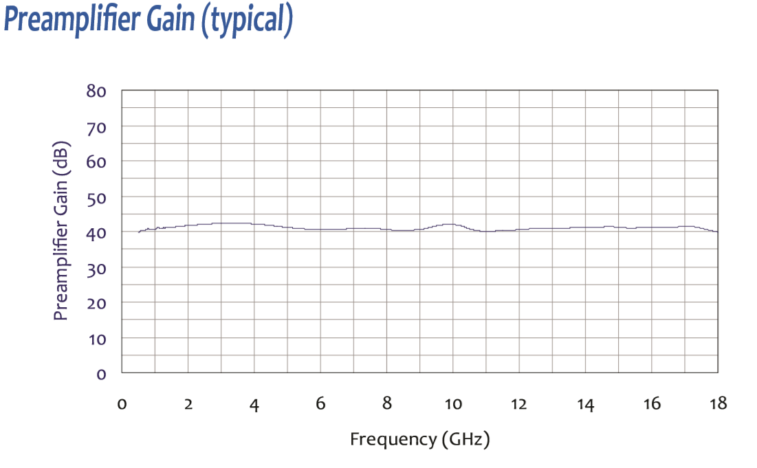
Wideband 40 dB Gain Preamplifier: 500 MHz - 18 GHz
PAM-118A — 500 MHz–18 GHz, ~40 dB gain (applications)
-
Place at the receive antenna to improve SNR for above-1 GHz radiated-emissions scans in chambers or OATS.
-
Overcome long coax loss and connector/switch path losses so weak DUT lines stay visible on the analyzer.
-
Speed up pre-scans by enabling wider RBW/VBW and shorter dwell times without losing low-level details.
-
Troubleshoot harmonics and spurs from clocks, DC-DC converters, and wireless modules (Wi-Fi/BT/cellular) in the 1–18 GHz range.
-
Pair with broadband horns/log-periodics to raise field-strength signals during antenna sweeps and chamber checks.
-
Stabilize sensitivity when a switch matrix, filters, or long cable runs sit between the antenna and the receiver.
-
Support 3 m/10 m measurements by lifting far-field signals that would otherwise sink into the noise floor.
-
Battery operation near the antenna minimizes ground-loop and power-lead coupling issues in quiet measurements.
-
Use on the receive path only; it is not intended for transmit/immunity chains.
- High Gain - 40 dB (Typical)
- Flat Response ±2.5 dB
- Low Noise Figure - 3 dB max
- Pout @ 1 dB Gain Compression - +12 dBm
- Battery Powered
- Frequency: 500 MHz to 18 GHz
- Gain: 40 dB (Typical)
- Gain Flatness: ± 2.5 dB
- RF Input/output: 50 Ω Precision N- type female
- VSWR ( Input/Output): 2.2:1 (max)
- Noise Figure: <3 dB @ 25°C
- Pout @ 1dB comp: +12 dBm (min)
- Reverse isolation: 40 dB (typical)
- Battery Pack: 6 Vdc, 2Ah NimH (rechargeable)
- DC Power supply: +15Vdc, 500 mA
- Size: 7.7 x 6.5 x 3.2 inches (184 x 156 x 77 mm)
- Weight: 2.5 lbs. (1.1Kg)
🔍 Not Sure Which Preamplifier You Need?
Find the perfect Com-Power preamplifier for your EMC testing needs with our interactive finder wizard. Filter by frequency range, gain, noise figure, and application to match your exact requirements.
Find Your Preamplifier →PAM-118A Wideband 40 dB Gain Microwave Preamplifier – Frequently Asked Questions
1. What is the PAM-118A preamplifier and what is it designed for?
The PAM-118A is a wideband, benchtop microwave preamplifier covering 500 MHz to 18 GHz with a typical gain of 40 dB and a noise figure below 3 dB. It is designed for modern EMC radiated emissions testing, microwave receive-chain improvement, and near-field probe amplification. Its role is to lift weak emissions well above the receiver noise floor across a very wide microwave band in a single unit, so labs do not need to swap between multiple narrower-band amplifiers during a full-spectrum scan.
2. Why is 500 MHz to 18 GHz coverage important in modern EMC testing?
Modern regulatory radiated emissions testing routinely extends into the multi-gigahertz range. FCC harmonic testing, CISPR 32 multimedia equipment, CISPR 11 industrial equipment, and many wireless device certifications require measurements up to 6, 12, or even 18 GHz depending on the product's highest internal frequency. A preamp that covers from 500 MHz to 18 GHz in one device eliminates the need to switch between multiple preamps during a sweep and reduces the risk of calibration errors at band edges.
3. How does the PAM-118A differ from the PAM-118H, PAM-6000, and PAM-840A?
The PAM-118A and PAM-118H share the same 500 MHz to 18 GHz range but differ in gain: the PAM-118A delivers 40 dB typical, while the PAM-118H delivers 50 dB typical. The PAM-118A is the better general-purpose choice because its lower gain reduces the risk of receiver overload on sites with strong ambients, and its 40 dB gain is plenty for most compliance measurements. The PAM-6000 covers only 1–6 GHz and is a narrower-band, more economical option if the lab does not need coverage above 6 GHz. The PAM-840A takes over at 18 GHz and extends to 40 GHz for millimeter-wave work.
4. How does the PAM-118A compare with separate narrower-band preamplifiers?
Using a single wideband preamp like the PAM-118A instead of two or three separate narrower-band units has significant workflow benefits. It eliminates connector changes during a full-spectrum scan, removes the band-edge overlap calibration complications that can cause amplitude discontinuities in a merged sweep, and simplifies the calibration and maintenance burden (one unit to send out for annual cal rather than multiple). The trade-off is that narrow-band preamps can sometimes achieve marginally better noise figure or flatness over their specific range, but for most compliance work the single-unit solution wins on productivity.
5. What are the biggest real-world workflow advantages of the PAM-118A?
The PAM-118A makes wider resolution bandwidths and faster pre-scans possible because its 40 dB gain gives measurements enough margin above receiver noise to allow shorter dwell times. It enables long cable runs from antenna to receiver in large chambers without sacrificing sensitivity. It supports 3 m and 10 m compliant test distances above 1 GHz, where cable loss would otherwise dominate. And it simplifies calibration logistics by covering the entire 500 MHz to 18 GHz range with a single calibration table.
6. What standards and frameworks does the PAM-118A support?
The PAM-118A is used in measurements under FCC Part 15, CISPR 11, CISPR 22/32, EN 55011, EN 55022/32, MIL-STD-461 (RE102 upper range), RTCA DO-160, ISO 11452 families, CISPR 25 automotive emissions, and various wireless certification standards (FCC 47 CFR Part 15 Subparts C, E, and others). Each unit ships with NIST-traceable calibration, and ISO/IEC 17025 accredited calibration is available for labs under accredited quality systems.
7. How is the PAM-118A used for radiated emissions measurements?
In receive mode, the PAM-118A sits between the receive antenna (horn, log-periodic, or broadband hybrid) and the EMI receiver or spectrum analyzer. Placing it as close to the antenna as possible is critical at these frequencies because microwave coaxial cable loss can reach 10 dB or more across long runs, and amplifying before the cable preserves signal-to-noise ratio. For antenna-mast setups where preamp placement on the boom is impractical, the PAM-118A can alternatively be placed at the receiver input, though with some sensitivity trade-off.
8. Can the PAM-118A be used in spectrum analyzer front-end applications?
Yes. Beyond formal EMC emissions work, the PAM-118A is commonly used as a general-purpose spectrum analyzer front end for any measurement where weak signals in the 500 MHz to 18 GHz range need to be lifted above instrument noise. This includes wireless device debug, harmonic measurement on transmitters, radar pulse characterization, satellite and broadcast signal monitoring, and microwave interference investigation. Its flat response (±2.5 dB) makes it usable for amplitude-accurate work with appropriate correction.
9. Why does a <3 dB noise figure matter at microwave frequencies?
At microwave frequencies, the thermal noise floor at the antenna is already quite low, and any noise added by the preamplifier directly limits how small a signal can be detected. A noise figure below 3 dB means the PAM-118A adds less than one dB to the system's effective noise temperature in most setups. By the Friis cascade formula, the overall system noise figure becomes very close to the preamp's own noise figure when the preamp is placed ahead of the receive chain — so a 3 dB noise figure in the preamp translates directly into a roughly 3 dB noise figure for the whole measurement system.
10. What does the +12 dBm output at 1 dB compression mean in practice?
The 1 dB compression point sets the upper limit of linear operation. Above P1dB, the preamp generates harmonic distortion and intermodulation products that a receiver will display as if they were real DUT emissions, producing false fails and confusing diagnostics. The PAM-118A's +12 dBm P1dB provides enough headroom for typical ambient signals and strong DUT fundamentals during radiated work. For very high-field environments, users should ensure the PAM-118A's input does not exceed about -28 dBm (40 dB below P1dB output), adding attenuators or filters where necessary.
11. What kinds of real-world products are good candidates for PAM-118A testing?
The PAM-118A covers essentially the full modern compliance band. Good candidates include Wi-Fi 2.4/5/6 GHz devices, Bluetooth, UWB radios, 5G sub-6 GHz and some FR1 devices, automotive radar at 24 GHz partially, keyfob systems, wireless charging products, HDMI and USB 3.x high-speed digital devices with upper-band harmonics, industrial mmWave sensors, medical imaging equipment with RF components, and aerospace avionics systems. For products that combine multiple wireless radios or high-speed digital interfaces, the PAM-118A's single-unit wideband coverage is particularly valuable.
12. Can the PAM-118A be used with near-field probes for troubleshooting?
Yes, though its gain may be more than is needed for very strong near-field signals. For high-frequency PCB troubleshooting in the 1–18 GHz range — tracking down clock harmonics, SerDes emissions, oscillator leakage, or wireless module RF leakage — the PAM-118A feeding from a near-field probe gives excellent sensitivity. For some very hot sources, users may want to add attenuation between the probe and preamp to avoid compressing the preamp. For routine lower-frequency near-field work, the smaller PAP-501 or PAM-103 may be more appropriate.
13. Why do individual calibration and NIST traceability matter for the PAM-118A?
At 18 GHz, tiny gain variations can translate into measurable amplitude errors, and broadband preamps naturally have more gain variation across their range than narrow-band units. Each PAM-118A is individually calibrated with gain-versus-frequency data traceable to NIST, and this correction is loaded into the EMI receiver or post-processing chain so that reported emissions reflect the antenna-port signal rather than the amplified signal. ISO/IEC 17025 accredited calibration is available for labs whose quality systems require it. Annual recalibration is the standard practice for microwave preamps.
14. What mechanical and RF interface details matter for daily use of the PAM-118A?
The PAM-118A uses precision 50-ohm N-type female connectors on input and output. N-type is robust for repeated connection cycles and provides good performance up to and above 18 GHz with a high-quality connector. The unit is compact (7.7" x 6.5" x 3.2", 2.5 lbs / 1.1 kg) with a built-in rechargeable 6 V NiMH battery pack. Battery operation allows antenna-side placement inside a shielded chamber without running power through the filter panel, and it eliminates a common source of chamber noise. The external DC power input is 15 V, 500 mA.
15. When is the PAM-118A a better choice than the PAM-118H?
The PAM-118A (40 dB gain) is a better choice than the PAM-118H (50 dB gain) in most situations. With 50 dB of gain, the PAM-118H can easily overload the EMI receiver on sites with strong ambient broadcast or cellular signals, and it leaves less input headroom before P1dB compression. Unless the measurement specifically needs ultra-low-level detection in a very quiet chamber — long-distance site attenuation, extremely small DUT emissions, or pulsed signal averaging — the PAM-118A's 40 dB gain gives a better balance of sensitivity and dynamic range. The PAM-118H is the specialty tool; the PAM-118A is the daily workhorse.
16. Why would an EMC lab choose the PAM-118A as a long-term investment?
The PAM-118A covers 500 MHz to 18 GHz in a single device with the gain, noise figure, flatness, calibration rigor, and mechanical robustness that modern compliance requires. It fits into virtually every microwave EMC measurement scenario a commercial lab will encounter, from classic FCC harmonic testing through the latest sub-6 GHz 5G and Wi-Fi product certification. Its battery operation, compact size, and durable N-type interface make it practical for both bench-top and chamber-side use. For labs whose testing has moved above 1 GHz — which is most labs today — the PAM-118A is typically the most broadly useful single preamp investment they can make.
Noise Floor, Noise Figure & System Sensitivity
17. What is the difference between noise floor and noise figure, and why does it matter for the PAM-118A?
These two terms are frequently confused but describe completely different things. Noise floor is a measured power level expressed in dBm or dBµV — it tells you the lowest signal amplitude that can be distinguished from background noise in a specific measurement setup at a specific resolution bandwidth. Noise figure is a property of the amplifier itself expressed in dB — it tells you how much the amplifier degrades the signal-to-noise ratio compared to a theoretical perfect amplifier at room temperature. The PAM-118A has a noise figure of <3 dB at 25°C, which is a device characteristic. The noise floor you actually see on your receiver depends on the preamp's noise figure, the RBW setting, cable losses ahead of the preamp, ambient temperature, and the receiver's own noise figure. A good preamp lowers the effective system noise figure, which in turn lowers the achievable measurement noise floor — but the two are not the same number.
18. How does the PAM-118A's noise figure affect the overall system noise floor?
The Friis cascade rule determines how the noise figures of chained components combine. When the PAM-118A with its <3 dB noise figure and 40 dB gain sits ahead of a cable and receiver, its gain dominates the cascade equation, and the system noise figure collapses to approximately the PAM-118A's own noise figure plus the loss of anything ahead of it (like a transient limiter or short cable to the antenna). The receiver's native noise figure, which might be 20–30 dB for an EMI receiver at 18 GHz, becomes nearly irrelevant because the signal has been amplified by 40 dB before reaching it. The result is a system noise floor that is roughly 20–30 dB lower than what the same receiver would produce without the preamp — which is the entire reason external preamps exist.
19. Why does a preamp with 40 dB gain not lower the noise floor by 40 dB?
This is a common intuition that is slightly wrong. Adding 40 dB of gain raises both the signal and the noise by 40 dB, so on the display the apparent noise floor rises rather than falls. What actually improves is the signal-to-noise ratio at the output relative to the receiver's own noise contribution. Because the receiver's noise now sits well below the amplified noise from the preamp and antenna, the overall sensitivity is limited by the preamp's noise figure rather than the receiver's. The net gain in measurement sensitivity is roughly (receiver noise figure − preamp noise figure − cable loss ahead of preamp). For a typical setup this works out to 15–25 dB of real sensitivity improvement, not 40 dB.
20. What limits the noise floor improvement I actually see with the PAM-118A in my setup?
Several factors can eat into the theoretical improvement. Cable loss between the antenna and the preamp directly adds to the effective system noise figure, so long coax on the input side destroys sensitivity — which is why antenna-side placement is essential. Temperature raises the thermal noise floor by about 0.01 dB per degree Celsius. Strong ambient signals outside the measurement band can cause receiver-input compression that raises the apparent noise floor through intermodulation. Poor connector torque on N-type connectors can add 0.5–1 dB of loss and intermittent contact that looks like noise. And resolution bandwidth directly scales the displayed noise: halving RBW drops the displayed noise floor by 3 dB regardless of preamp performance.
ESD Protection & Preamp Safety
21. Why are microwave preamplifiers like the PAM-118A vulnerable to static electricity?
Microwave preamplifiers use low-noise GaAs or GaN transistors at their front end, which are selected specifically for their low noise figure and high gain per stage. These same device characteristics — thin gate oxide, small channel dimensions, very high input impedance — make them extraordinarily sensitive to electrostatic discharge (ESD). A static discharge of just a few hundred volts, which a person may not even feel, can punch through the gate oxide of a low-noise front-end FET and either completely kill the device or, worse, damage it subtly so that the gain drops by a few dB or the noise figure rises by a few dB without any other visible failure. Labs have had preamps come back from calibration with "passing" gain readings but significantly degraded noise figure because of prior undetected ESD damage.
22. How does static electricity reach a preamp connected to an antenna through a coaxial cable?
This is the most common failure mode in EMC labs. An operator handles the antenna — mounts it on a tripod, adjusts its position, changes polarization — and in doing so accumulates a static charge on their body (from walking across carpet, removing a sweater, or just moving around in a dry room). When they touch the antenna, the static discharges through the antenna element, into the coaxial feedline, and directly into the PAM-118A's RF input. The coaxial cable is a low-impedance path that efficiently delivers the entire ESD pulse to the preamp's sensitive front end. Because the discharge happens in nanoseconds, there is essentially no time for the preamp's internal protection to respond, and damage is instant. The operator may not notice anything unusual until later when measurements look wrong.
23. What practical steps prevent static from damaging the PAM-118A through the antenna?
Adopt a disciplined ESD protocol any time the antenna or RF chain is being handled:
• Ground yourself before touching the antenna — wear an ESD wrist strap connected to the chamber ground, or at minimum touch a grounded metal surface (the chamber wall, a grounded bench, the antenna mast base) immediately before handling the antenna.
• Disconnect the preamp input before making major antenna adjustments. A disconnected preamp input is immune to ESD through the antenna path.
• Use an ESD-rated inline attenuator or limiter at the preamp input if frequent antenna handling is unavoidable. Even a 3 dB attenuator provides some protection.
• Cap the antenna connector when it is not connected to the preamp — this prevents static buildup on the center pin.
• Humidify the chamber to 40–50% relative humidity if possible; ESD events are dramatically less common at normal humidity than in dry environments.
• Turn off the preamp before connecting or disconnecting RF cables. Unpowered preamps survive ESD events better than powered ones.
24. What about ESD through the DC power input or chassis of the PAM-118A?
Less common than the RF path but still possible. Best practices: plug the PAM-118A's DC adapter into a grounded outlet, not a floating or ungrounded power strip. When operating on battery, the chassis can float relative to the chamber ground — use a chassis ground strap to the chamber reference plane if the preamp is operating inside a chamber. Avoid carrying the preamp across a carpeted area and setting it directly into the RF chain without first touching it to a grounded surface. If the preamp has been stored or shipped, let it sit on a grounded bench for a few seconds before connecting any cables to it.
25. How do I protect the PAM-118A during antenna polarization changes and tripod adjustments?
This is a high-risk moment because the operator is actively handling the antenna. Recommended workflow: (1) before approaching the antenna, touch a grounded metal surface to discharge yourself; (2) if the test is paused, power down the preamp or disconnect its input cable; (3) make the antenna adjustment; (4) touch the grounded surface again before reconnecting or powering up the preamp. This adds maybe 15 seconds to each adjustment but dramatically reduces ESD risk. For automated antenna masts, the same principle applies at maintenance time — ground yourself before handling cables or connectors on the mast.
26. How do I tell if the PAM-118A has been damaged by ESD?
Subtle ESD damage does not always produce a dead preamp; often it produces a degraded one. Warning signs include: gain that reads lower than the calibration data by 1–3 dB across the full band or in a specific frequency range; noise figure that has clearly increased (the noise floor with the preamp in circuit is higher than it used to be for the same RBW); frequency response ripple that was not present before; gain that drifts with temperature more than it used to; or increased current draw from the battery or DC supply. If any of these symptoms appear, the preamp should be sent to Com-Power for recalibration and evaluation. If damage is confirmed, repair is often possible — input stages can sometimes be replaced without losing the rest of the unit's calibration history.
27. What should I do immediately if I suspect ESD has occurred on the PAM-118A input?
Power down the preamp and disconnect it from the measurement chain. Run a quick sanity check against a known-good reference signal (a comb generator or a calibrated source) to see if gain is still within specification across the band. Compare the measured gain curve to the original calibration data. If gain is uniformly correct, the preamp may have survived. If gain is off, noise figure appears higher, or the response shape has changed, send the unit to Com-Power for evaluation rather than continuing to use it — a compromised preamp produces measurements that look plausible but are systematically wrong, which is worse than a unit that clearly does not work. Com-Power offers both 17025 accredited and NIST-traceable recalibration, and repair service for damaged units.


Quote Request
Other EMC Test Equipment
- Absorbing Clamps
- Antenna Kits
- Antenna Masts - Automated and Manual
- Antennas
- Bulk Current Injection probes
- CDNs - Coupling Decoupling Network
- Comb Generators
- Conducted Immunity Test Systems
- Current Monitor Probes
- Current Probe Calibration Fixtures
- EM Clamps
- Feed Through Capacitor
- ISNs - Impedance Stabilization Network
- LISNs - Single Phase
- LISNs - TEMPEST
- LISNs - Three Phase
- Magnetic Field Generator
- Near Field Probes
- Power Amplifiers
- Pre-compliance Emissions Test Systems
- Preamplifiers
- Spectrum Analyzers
- Surge Generators
- System Controllers
- Transient Limiters
- Tripods For EMC
- Turntables